VW Golf 1.4 BCA: EGR flow malfunction

Vehicle: VW Golf | System: Exhaust Gas Recirculation | Codes: P0400, P0401

Overview

Symptom: MIL illuminated. Otherwise the customer has no performance issues.

Primary Cause: No EGR flow was detected by the ECU and a no flow malfunction was recorded. Another workshop replaced the EGR valve but a day or so later the MIL came back on.

Some other attempts were made to get to the bottom of the issue but without success.

When I received the car I could see a new EGR valve — brand unknown — and there was a new metal pipe that connects the EGR to the back of the intake manifold chamber.

The Fix: Looking at live data I could not see any EGR effect when the valve should have been open. After a few checks I could hear the valve open and close but it didn’t effect the flow. Stripping it down to see what was blocking or restricting the flow I noticed the gasket on the EGR valve to the exhaust side was on the wrong way around and actually blocking the flow.

1. Diagnostic Fault Interrogation

When the car came into the workshop it had been worked on elsewhere, first time it got a new EGR valve fitted and when that didn’t fix the problem a second one was fitted.

It then went to another workshop and it couldn’t be solved, I believe they fitted a new outlet pipe from the valve to the inlet manifold.

Carrying out a number of tests I could not see any flow when the valve was supposed to be open.

I confirmed using VCDS and an Oscilloscope that the EGR was receiving a command from the ECU.

One simple test of shop air directed back through the exhaust with a delta sensor in the intake manifold showed that when the EGR was commanded open it didn’t allow air through.

2. System Analysis

These systems are as simple as they come, a valve is commanded open to allow inert gas into the intake and because this is an SD engine it is monitored by the MAP sensor. When the gas is passed into the manifold the pressure increases so the vacuum decreases and the MAP sensor reports back to the ECU, the ECU is expecting to see this so as long as it sees that signal it’s happy. However if it commands the EGR and doesn’t see that feedback it will set a code, usually a P0401.

3. Repairing the fault

Not seeing any flow from my tests I decided that we had some sort of restriction even though all the parts were new.

I believed that I was going to find a faulty part — I highly suspected this no name EGR valve — but when I removed the valve assembly I immediately saw the issue — the gaskets which are not interchangeable were on the wrong way around and acting as a blanking plate basically.

I don’t have any photos from this job, they were deleted, this is a stock image

4. Verifying the fix

After placing the gasket to its correct orientation I again tried my shop air blast from the exhaust system back through the valve. I commanded the valve open and saw my delta sensor fluctuate.

It didn’t do that before — obviously after what I found — but it was nice to prove my set up and actually see flow happen.

I test drove the car after the fix and it worked as it should. I kept using it until it set its drive monitor which was absolute proof that we hit the nail on the head with this weird one.

Such an easy mistake and an easy one to overlook unless you have a solid test plan.
VW Caddy 2.0 TDI: Intermittent No-Start & Loss of Terminal 15 Power

Vehicle: VW Caddy 2.0 TDI | System: Engine Management / Power Distribution

Overview

Symptom: Engine cranks with no start condition; sporadic instrument cluster behavior.

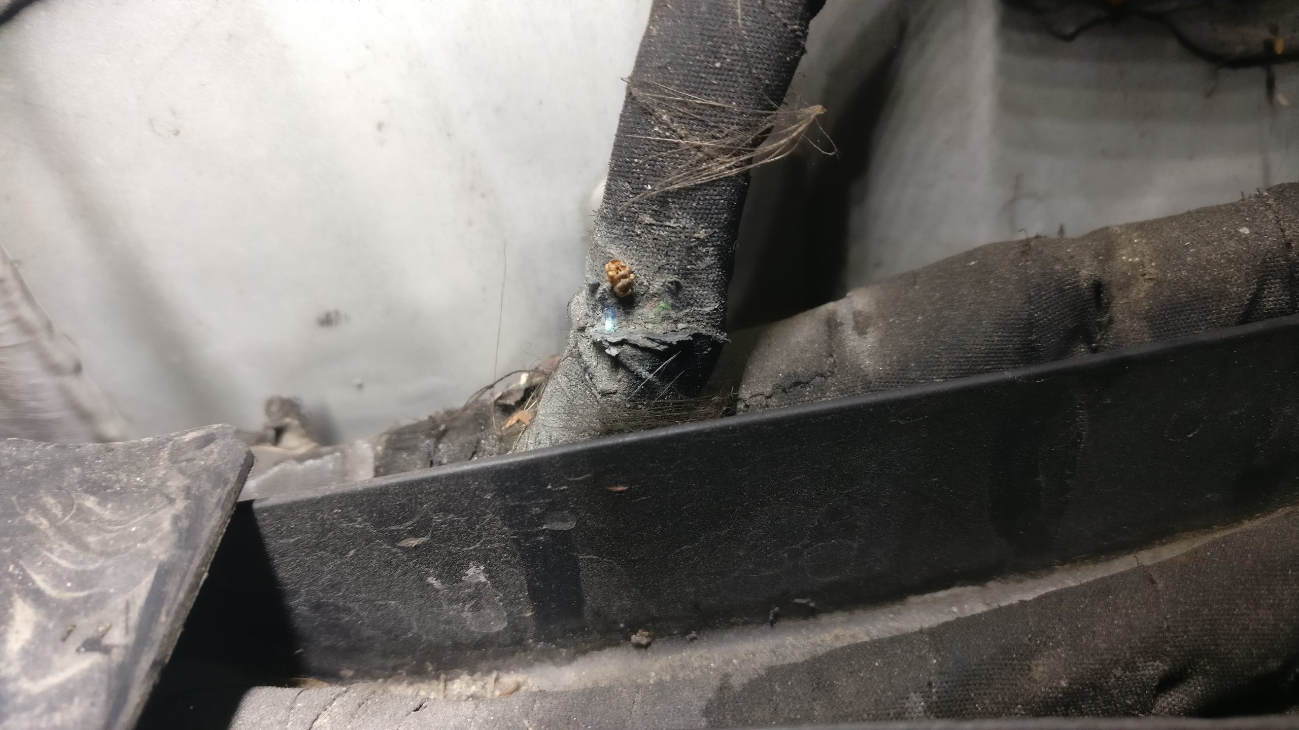
Primary Cause: Fractured and corroded (0.35mm²) bl/ge wire in the engine bay harness causing intermittent Terminal 15 main power relay drop-out to the ECM.

The Fix: Find the offending wire in the harness, behind the battery area, open the harness at that point and repair with a soldered joint and wrap in waterproof heat connector shield. Re-tape harness and re-route/secure it in place.

1. Diagnostic Fault Interrogation

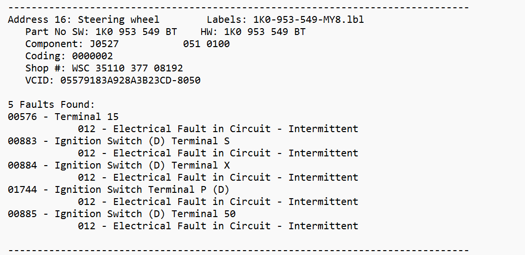
Initial connection with VCDS scan tool revealed multiple intermittent electrical circuit faults stored in the Steering Wheel Control Module (J0527), specifically targeting Terminal 15, Terminal S, and Terminal 50 ignition switches. A complete scan of the Engine Control Module (J623) returned no fault codes.

Figure 1: VCDS fault log for Address 16 (Steering Wheel) showing Terminal 15 electrical circuit faults.

2. Wiring Diagram Analysis

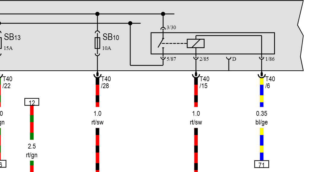
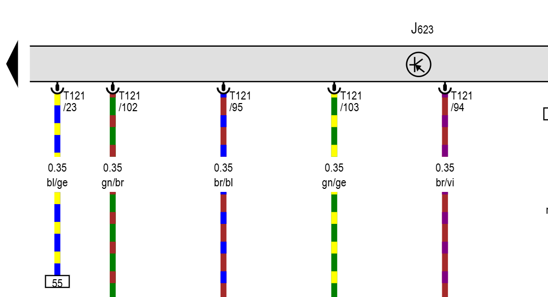
Tracing the electrical schematics on ERWIN identified pin 23 on the ECM connector T121 (0.35mm² blue/yellow wire). This trace feeds back through track 55 to fuse SB10 and the main power supply relay logic inside the E-box. A drop in signal integrity on this specific line starves the ECU of key-on recognition.

Figure 2.1: Relay & Fuse SB10 distribution schematic.
Figure 2.2: J623 ECM connector T121 pin 23 trace.

3. Oscilloscope & Circuit Testing

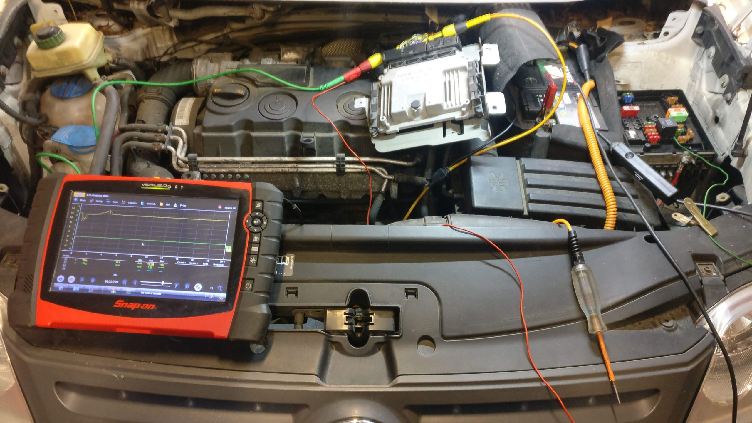
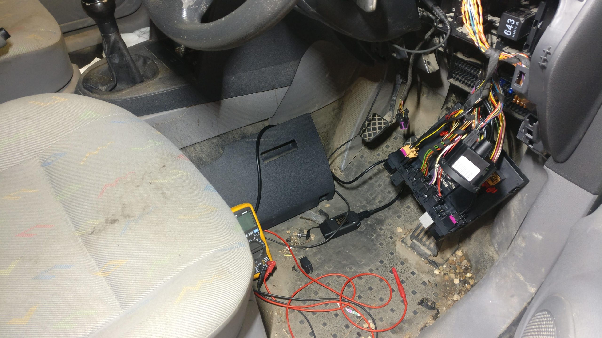
With the in-cabin lower dash trim removed to monitor switch logic, a lab scope was connected to the engine bay junction. Monitoring voltage across pin 23 while flexing the harness revealed intermittent voltage drops under load, confirming an open circuit downstream of the control module. I then jumped a test light from the relay to the ECU pin 23 and my power came back on demand.

Figure 3.1: Scope hookup and breakout leads on engine ECU harness.
Figure 3.2: Interior relay panel access for switch logic testing.

4. Harness Unwrapping & Defect Isolation

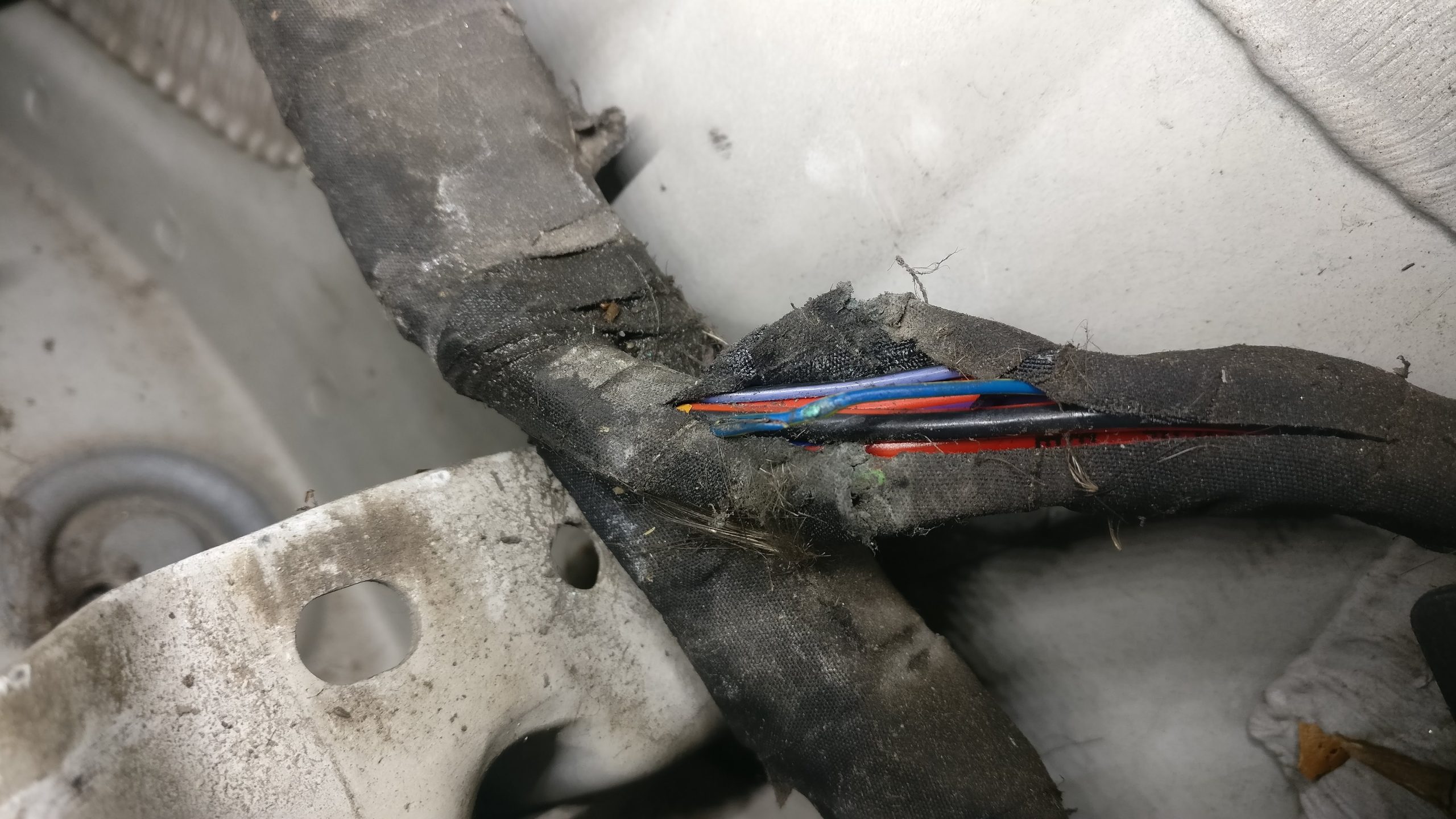
Stripping the tape along the chassis rail bundle exposed severe green copper oxide (verdigris) rot and a complete fracture inside the (0.35mm²) bl/ge wire. Rubbing inside the loom had compromised the insulation, allowing moisture to corrode the copper core.

Figure 4.1: Broken copper wire found inside stripped loom.
Figure 4.2: Point of loom chafing along the chassis mount.

5. Repair & Verification

The damaged section was cut out, spliced with a soldered inline joint, and sealed using adhesive-lined heat shrink. The entire engine loom section was re-wrapped in Tesa harness tape, re-secured, and cleared of all fault codes. Post-repair cranking tests showed instant start-up and rock-solid power feeds on the scope.

It always reads like an easy logical process after the job is done, but this wasn’t as straight forward as it may look. But I did enjoy the process. This is the first time I’ve written a case study matter of fact piece — I usually like to write in story form but it wasn’t working for me on this one, a lot of this was from memory of a job I did a number of years ago — and it does make it all seem mechanical and robotic, but it’s to the point and hopefully helpful even? I might do more of these concise type posts in the future.

From Kia to Mercedes: It’s All Just Physics Under the Hood

I choose to work on VW, Audi and Mercedes but that’s not all I do.

I CAN work on Kia, Toyota, Ford, Chevy, Jeep etc.

Because as we know a lot of this stuff was built on global platforms from at least the early 2000’s.

I remember reading a piece about the MK 1 Ford Focus and how it was a breakthrough because it was a global platform.

So from Fiat wiring being in just about every Chrysler product to that Ecotec GM engine being in a lot of the Chevrolet or whatever else it appears in, I feel I’ve seen most of this stuff, and what I haven’t seen is quickly summed up by applying basic common theory.

3, 5, 6 ,8 or even 12 cylinders, they all need fuel, air, compression and a way of igniting before they can do anything.

My point being it doesn’t matter what you work on, if you apply the basics and do it right the rest is easy and it’s not a question of what badge it carries.

Misfire no Codes – Suzuki Splash 1.2L Petrol K12B

What’s the problem?

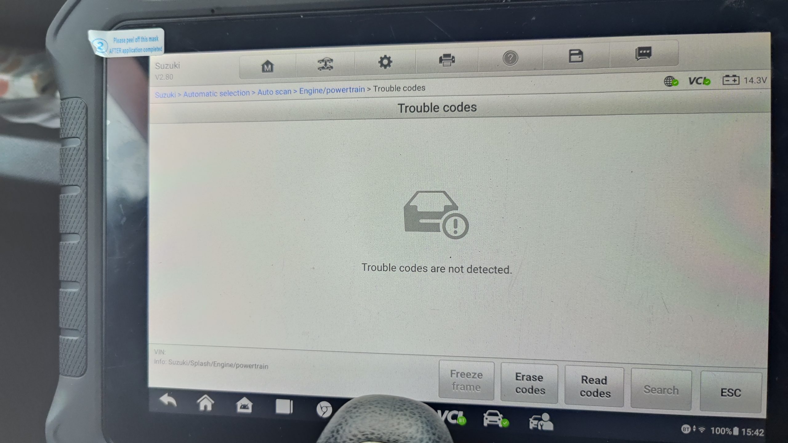
This Suzuki came into the workshop with an intermittent misfire. It wasn’t evident on tickover or when I’d snap the throttle while stationary. But when I drove it any distance, I could feel it. Okay, so that’s the customer’s complaint confirmed. The next step was to connect a scan tool and check for diagnostic trouble codes (DTCs).

No codes?

Despite the misfire, no DTCs were stored. With no codes, a different diagnostic approach will be required to prove the fault. I’m suspicious of an ignition coil but I want to prove it to be sure.

Suzuki Swift No Codes For A Misfire On The Scan Tool
Continue Reading
Diagnostic View