Overview
Symptom: Engine cranks with no start condition; sporadic instrument cluster behavior.
Primary Cause: Fractured and corroded (0.35mm²) bl/ge wire in the engine bay harness causing intermittent Terminal 15 main power relay drop-out to the ECM.
The Fix: Find the offending wire in the harness, behind the battery area, open the harness at that point and repair with a soldered joint and wrap in waterproof heat connector shield. Re-tape harness and re-route/secure it in place.
1. Diagnostic Fault Interrogation
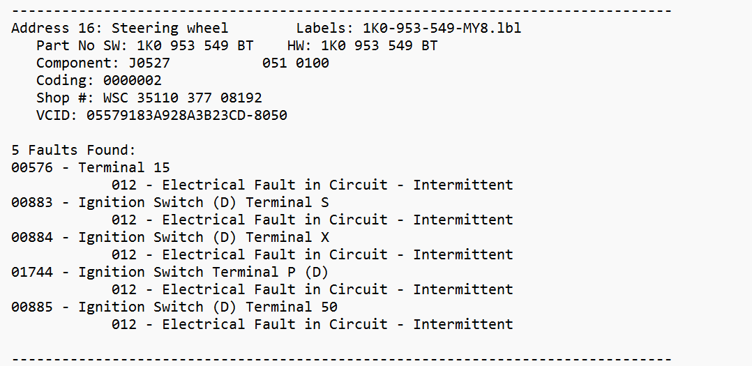
Initial connection with VCDS scan tool revealed multiple intermittent electrical circuit faults stored in the Steering Wheel Control Module (J0527), specifically targeting Terminal 15, Terminal S, and Terminal 50 ignition switches. A complete scan of the Engine Control Module (J623) returned no fault codes.
2. Wiring Diagram Analysis
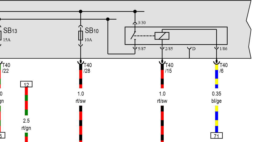
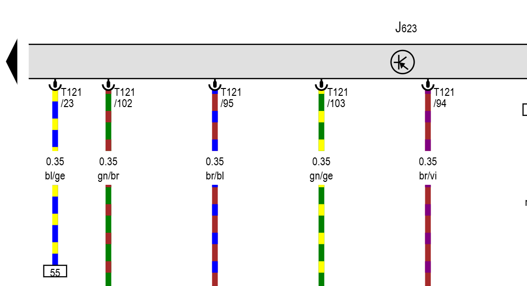
Tracing the electrical schematics on ERWIN identified pin 23 on the ECM connector T121 (0.35mm² blue/yellow wire). This trace feeds back through track 55 to fuse SB10 and the main power supply relay logic inside the E-box. A drop in signal integrity on this specific line starves the ECU of key-on recognition.
3. Oscilloscope & Circuit Testing
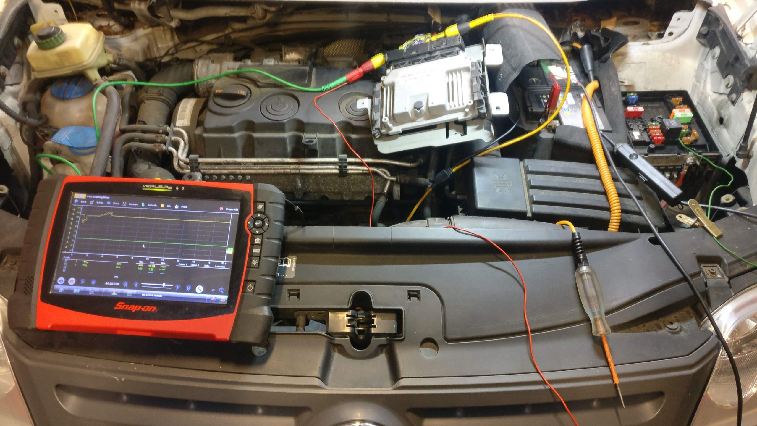
With the in-cabin lower dash trim removed to monitor switch logic, a lab scope was connected to the engine bay junction. Monitoring voltage across pin 23 while flexing the harness revealed intermittent voltage drops under load, confirming an open circuit downstream of the control module. I then jumped a test light from the relay to the ECU pin 23 and my power came back on demand.
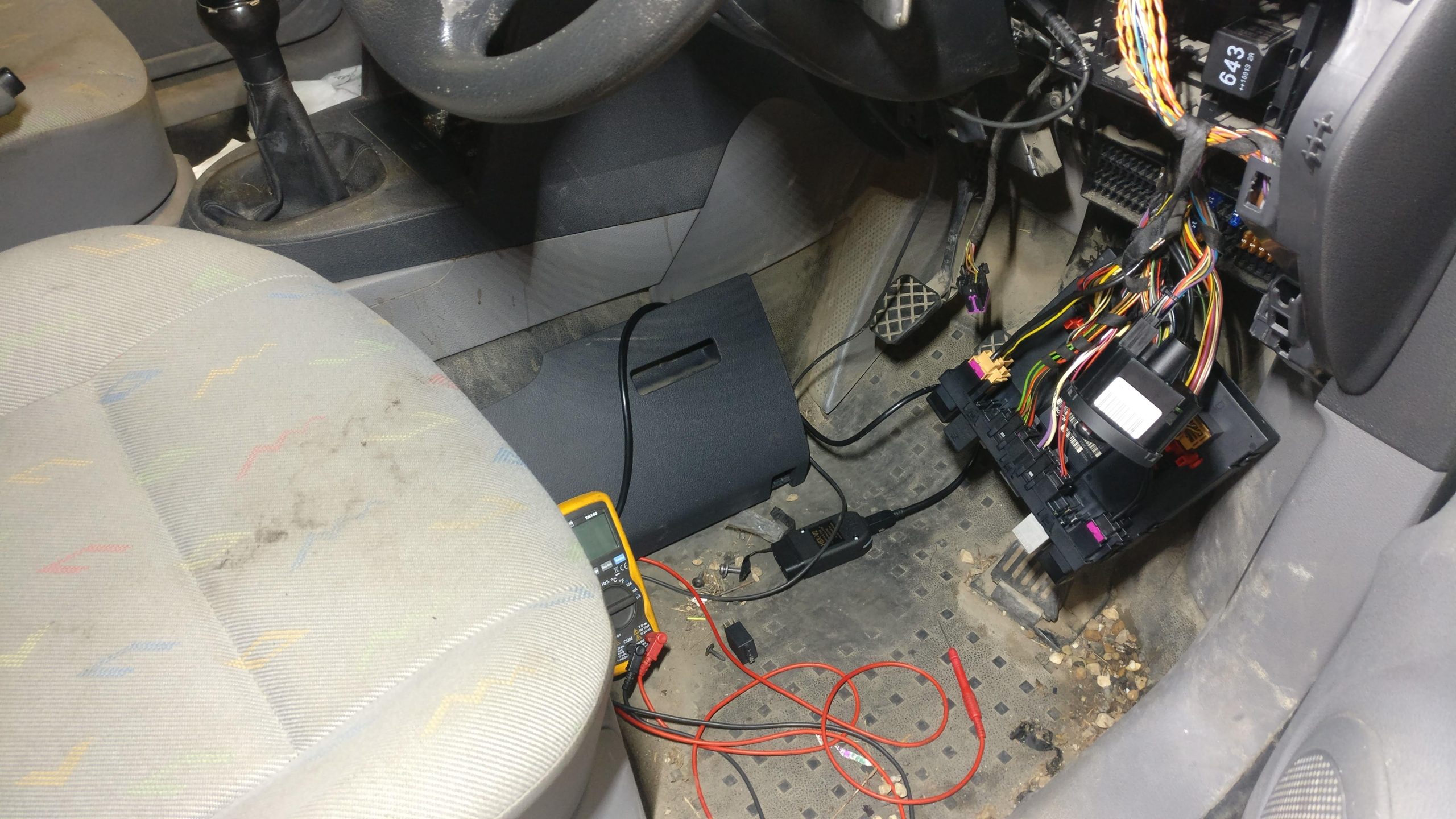
4. Harness Unwrapping & Defect Isolation
Stripping the tape along the chassis rail bundle exposed severe green copper oxide (verdigris) rot and a complete fracture inside the (0.35mm²) bl/ge wire. Rubbing inside the loom had compromised the insulation, allowing moisture to corrode the copper core.
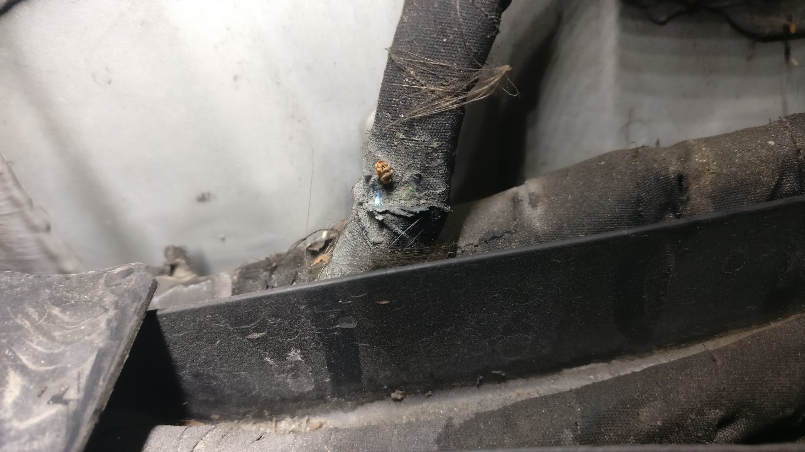
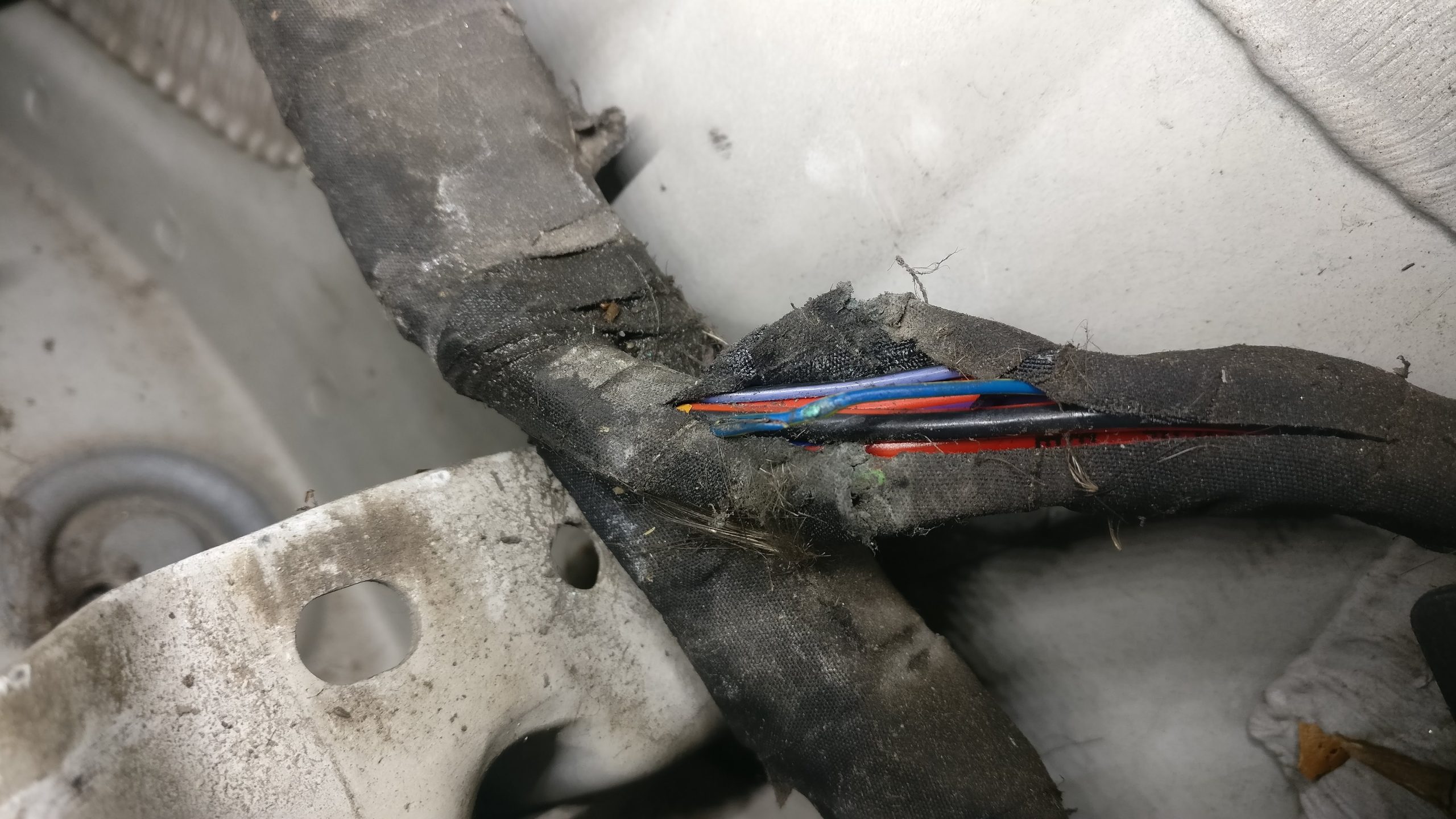
5. Repair & Verification
The damaged section was cut out, spliced with a soldered inline joint, and sealed using adhesive-lined heat shrink. The entire engine loom section was re-wrapped in Tesa harness tape, re-secured, and cleared of all fault codes. Post-repair cranking tests showed instant start-up and rock-solid power feeds on the scope.
It always reads like an easy logical process after the job is done, but this wasn’t as straight forward as it may look. But I did enjoy the process. This is the first time I’ve written a case study matter of fact piece — I usually like to write in story form but it wasn’t working for me on this one, a lot of this was from memory of a job I did a number of years ago — and it does make it all seem mechanical and robotic, but it’s to the point and hopefully helpful even? I might do more of these concise type posts in the future.
Leave a Reply
You must be logged in to post a comment.